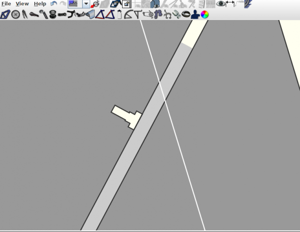
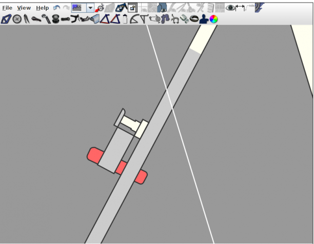
First, the rear canti bosses don't take on the color of the stays in "stays" color schemes, but rather they remain the main color (i.e. "1st"). This does not happen with schemes like "spear" and "two/three color angled."
Second, when modeling centerpull brakes with cantilevers I found that values of PY less than D/2 create a blank space in the middle of the canti pivot. I expect this is because the arm is drawn from the top of the pivot regardless of the PY value. An easy way to allow weirdos like me to model centerpull brakes would be to give extensions above and below the pivot their own dimensions and ignore values for those dimensions less than D/2.


Thanks for the heads up on the canti boss colour issue. Also thanks for the note about center pull brakes. To clarify for others, in the vast majority of cases where cantilever bosses are used, the brake pads are located above the boss. This is true for V-brakes and even for the most common variety of center pull cantilever brakes. However, as pointed out, some brakes that employ cantilever style bosses do have the pads located below the bosses. Examples would include U-brakes or the Paul centerpull brake with the braze-on option shown below. As per your recommendation, I will account for this scenario in the next update of BikeCAD.
In the meantime, I think when you referred to dimension D you must have meant dimension BW. Furthermore to recreate your screen capture above, I needed to set dimension AL to a negative value. In the future I will change things so there will be no need to use a negative value for AL.
I definitely meant D. I had BW set to zero in my first post for aesthetic reasons. Here's an example with AL = 5 where D = 18 and BW = 30. Note the notch that results from AL < D/2 in the circled cantilever pivot.
Your use of what appears to be one of my models for your example reminds me of another problem I noticed. If I set a model as unpublished, the unpublished label occludes the model title like so:
Thanks for such a fast response. I look forward to seeing how you implement the centerpull brakes.
The cantilever brake option was initially set up to model typical cantilever brakes and V-brakes where the brake pad is located above the brake boss. The dimension diagram in the Brakes dialog box demonstrates how these brakes should be configured.
In version 9.15, I've changed things to accommodate U-brakes. Now, if you enter a negative value for PY (the vertical position of the brake pad), the dimensions BX and BW will control the size of the brake arm as shown below:
I've also corrected the Stays paint scheme to include the brake boss as you can see above.
Finally, you should also notice in your My Designs section that I've modified the display of unpublished designs as requested.